what kind of wire does dish use to antenna
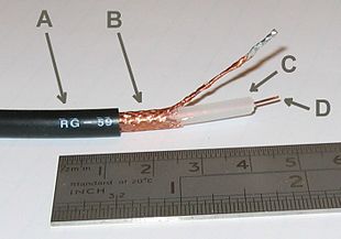
RG-59 flexible coaxial cable equanimous of:
- Outer plastic sheath
- Woven copper shield
- Inner dielectric insulator
- Copper core
Coaxial cable, or coax (pronounced ) is a type of electrical cable consisting of an inner usher surrounded past a concentric conducting shield, with the two separated by a dielectric (insulating material); many coaxial cables too accept a protective outer sheath or jacket. The term coaxial refers to the inner conductor and the outer shield sharing a geometric axis.
Coaxial cable is a type of transmission line, used to carry high-frequency electric signals with low losses. It is used in such applications as phone trunk lines, broadband internet networking cables, high-speed computer data busses, cable tv signals, and connecting radio transmitters and receivers to their antennas. It differs from other shielded cables because the dimensions of the cable and connectors are controlled to give a precise, constant usher spacing, which is needed for it to role efficiently every bit a manual line.
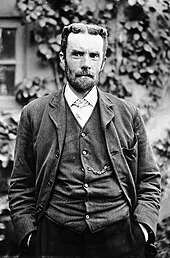
In his 1880 British patent, Oliver Heaviside showed how coaxial cable could eliminate signal interference betwixt parallel cables.
Coaxial cable was used in the first (1858) and post-obit transatlantic cable installations, only its theory was not described until 1880 past English physicist, engineer, and mathematician Oliver Heaviside, who patented the design in that year (British patent No. 1,407).[1]
Applications [edit]
Coaxial cable is used equally a transmission line for radio frequency signals. Its applications include feedlines connecting radio transmitters and receivers to their antennas, computer network (eastward.g., Ethernet) connections, digital audio (S/PDIF), and distribution of cable television signals. 1 advantage of coaxial over other types of radio manual line is that in an platonic coaxial cable the electromagnetic field carrying the point exists only in the space between the inner and outer conductors. This allows coaxial cable runs to be installed next to metal objects such as gutters without the power losses that occur in other types of transmission lines. Coaxial cable also provides protection of the signal from external electromagnetic interference.
Description [edit]

Coaxial cable cutaway (not to scale)
Coaxial cable conducts electrical betoken using an inner usher (unremarkably a solid copper, stranded copper or copper plated steel wire) surrounded by an insulating layer and all enclosed by a shield, typically one to iv layers of woven metal complect and metallic tape. The cablevision is protected by an outer insulating jacket. Normally, the outside of the shield is kept at ground potential and a signal carrying voltage is applied to the center conductor. The advantage of coaxial blueprint is that with differential manner, equal button-pull currents on the inner conductor, and inside of the outer conductor, the signal's electric and magnetic fields are restricted to the dielectric, with little leakage outside the shield. Further, electrical and magnetic fields outside the cable are largely kept from interfering with signals inside the cable, if diff currents are filtered out at the receiving end of the line. This property makes coaxial cable a adept choice both for carrying weak signals, that cannot tolerate interference from the environs, and for stronger electrical signals, that must not be allowed to radiate or couple into next structures or circuits.[2] Larger bore cables and cables with multiple shields have less leakage.
Common applications of coaxial cable include video and CATV distribution, RF and microwave transmission, and estimator and instrumentation data connections.[3]
The characteristic impedance of the cable ( ) is determined by the dielectric abiding of the inner insulator and the radii of the inner and outer conductors. In radio frequency systems, where the cable length is comparable to the wavelength of the signals transmitted, a compatible cablevision feature impedance is important to minimize loss. The source and load impedances are called to match the impedance of the cablevision to ensure maximum power transfer and minimum standing wave ratio. Other important backdrop of coaxial cable include attenuation every bit a function of frequency, voltage treatment capability, and shield quality.[two]

Construction [edit]
Coaxial cablevision design choices affect concrete size, frequency performance, attenuation, power treatment capabilities, flexibility, strength, and cost. The inner conductor might be solid or stranded; stranded is more flexible. To get better high-frequency functioning, the inner conductor may be silver-plated. Copper-plated steel wire is often used as an inner conductor for cable used in the cable TV industry.[4]
The insulator surrounding the inner conductor may be solid plastic, a foam plastic, or air with spacers supporting the inner wire. The properties of the dielectric insulator decide some of the electric backdrop of the cable. A common choice is a solid polyethylene (PE) insulator, used in lower-loss cables. Solid Teflon (PTFE) is also used as an insulator, and exclusively in plenum-rated cables.[ citation needed ] Some coaxial lines use air (or some other gas) and have spacers to keep the inner conductor from touching the shield.
Many conventional coaxial cables utilise braided copper wire forming the shield. This allows the cable to exist flexible, only it also means at that place are gaps in the shield layer, and the inner dimension of the shield varies slightly considering the braid cannot exist flat. Sometimes the braid is silver-plated. For meliorate shield performance, some cables take a double-layer shield.[4] The shield might be simply two braids, merely it is more than common now to take a sparse foil shield covered past a wire braid. Some cables may invest in more than two shield layers, such as "quad-shield", which uses four alternating layers of foil and braid. Other shield designs sacrifice flexibility for better performance; some shields are a solid metallic tube. Those cables cannot be aptitude sharply, every bit the shield will kink, causing losses in the cable. When a foil shield is used a small wire conductor incorporated into the foil makes soldering the shield termination easier.
For high-ability radio-frequency transmission up to nigh ane GHz, coaxial cable with a solid copper outer conductor is bachelor in sizes of 0.25 inch upward. The outer conductor is corrugated like a bellows to let flexibility and the inner conductor is held in position by a plastic spiral to estimate an air dielectric.[4] One brand proper noun for such cable is Heliax.[five]
Coaxial cables crave an internal structure of an insulating (dielectric) cloth to maintain the spacing between the center usher and shield. The dielectric losses increase in this guild: Ideal dielectric (no loss), vacuum, air, polytetrafluoroethylene (PTFE), polyethylene foam, and solid polyethylene. An inhomogeneous dielectric needs to be compensated past a not-circular usher to avert electric current hot-spots.
While many cables have a solid dielectric, many others have a foam dielectric that contains as much air or other gas equally possible to reduce the losses past allowing the use of a larger diameter centre usher. Foam coax volition have about 15% less attenuation merely some types of foam dielectric can absorb moisture—especially at its many surfaces — in humid environments, significantly increasing the loss. Supports shaped like stars or spokes are even better but more expensive and very susceptible to wet infiltration. Still more than expensive were the air-spaced coaxials used for some inter-city communications in the mid-20th century. The middle conductor was suspended past polyethylene discs every few centimeters. In some low-loss coaxial cables such as the RG-62 type, the inner conductor is supported by a spiral strand of polyethylene, then that an air space exists betwixt almost of the conductor and the within of the jacket. The lower dielectric constant of air allows for a greater inner diameter at the same impedance and a greater outer diameter at the aforementioned cutoff frequency, lowering ohmic losses. Inner conductors are sometimes silver-plated to polish the surface and reduce losses due to peel effect.[4] A rough surface extends the current path and concentrates the current at peaks, thus increasing ohmic loss.
The insulating jacket can be made from many materials. A common choice is PVC, but some applications may require fire-resistant materials. Outdoor applications may require the jacket to resist ultraviolet light, oxidation, rodent damage, or straight burial. Flooded coaxial cables utilise a water-blocking gel to protect the cable from water infiltration through minor cuts in the jacket. For internal chassis connections the insulating jacket may exist omitted.
Indicate propagation [edit]
Twin-lead transmission lines have the belongings that the electromagnetic wave propagating down the line extends into the space surrounding the parallel wires. These lines have low loss, but also accept undesirable characteristics. They cannot be bent, tightly twisted, or otherwise shaped without irresolute their feature impedance, causing reflection of the signal back toward the source. They also cannot be buried or run forth or fastened to anything conductive, as the extended fields volition induce currents in the nearby conductors causing unwanted radiations and detuning of the line. Collision insulators are used to keep them away from parallel metal surfaces. Coaxial lines largely solve this problem by confining virtually all of the electromagnetic wave to the expanse within the cablevision. Coaxial lines tin therefore exist bent and moderately twisted without negative effects, and they can be strapped to conductive supports without inducing unwanted currents in them, and so long every bit provisions are made to ensure differential mode betoken push button-pull currents in the cablevision.
In radio-frequency applications upward to a few gigahertz, the wave propagates primarily in the transverse electric magnetic (TEM) mode, which ways that the electric and magnetic fields are both perpendicular to the direction of propagation. Nonetheless, above a certain cutoff frequency, transverse electrical (TE) or transverse magnetic (TM) modes can also propagate, as they practice in a hollow waveguide. Information technology is usually undesirable to transmit signals above the cutoff frequency, since it may crusade multiple modes with different phase velocities to propagate, interfering with each other. The outer bore is roughly inversely proportional to the cutoff frequency. A propagating surface-wave mode that does not involve or require the outer shield just only a single cardinal conductor also exists in coax but this mode is effectively suppressed in coax of conventional geometry and common impedance. Electric field lines for this [TM] mode have a longitudinal component and crave line lengths of a half-wavelength or longer.
Coaxial cablevision may be viewed as a type of waveguide. Ability is transmitted through the radial electrical field and the circumferential magnetic field in the TEM00 transverse mode. This is the dominant mode from naught frequency (DC) to an upper limit determined by the electric dimensions of the cable.[6]
Connectors [edit]

A male F-blazon connector used with common RG-6 cable

The ends of coaxial cables usually terminate with connectors. Coaxial connectors are designed to maintain a coaxial class across the connection and accept the same impedance as the fastened cable.[4] Connectors are normally plated with high-conductivity metals such as silver or tarnish-resistant golden. Due to the skin outcome, the RF point is only carried past the plating at higher frequencies and does not penetrate to the connector body. Silver however tarnishes quickly and the silver sulfide that is produced is poorly conductive, degrading connector performance, making silvery a poor choice for this application.[7]
Important parameters [edit]
Coaxial cable is a item kind of transmission line, then the excursion models developed for general transmission lines are advisable. Encounter Telegrapher'due south equation.
![]()
Schematic representation of the elementary components of a transmission line
![]()
Schematic representation of a coaxial transmission line, showing the characteristic impedance
Concrete parameters [edit]
In the post-obit section, these symbols are used:
Fundamental electrical parameters [edit]
- Shunt capacitance per unit length, in farads per metre.[8]

- Series inductance per unit length, in henrys per metre.

- Series resistance per unit of measurement length, in ohms per metre. The resistance per unit length is just the resistance of inner usher and the shield at low frequencies. At higher frequencies, pare effect increases the constructive resistance by circumscribed the conduction to a thin layer of each conductor.
- Shunt conductance per unit of measurement length, in siemens per metre. The shunt conductance is usually very pocket-size because insulators with good dielectric properties are used (a very low loss tangent). At loftier frequencies, a dielectric can take a significant resistive loss.
Derived electrical parameters [edit]
- Characteristic impedance in ohms (Ω). The complex impedance Z of an infinite length of manual line is:
-
- Where R is the resistance per unit length, Fifty is the inductance per unit length, G is the conductance per unit length of the dielectric, C is the capacitance per unit length, and s = jω = j2πf is the frequency. The "per unit length" dimensions cancel out in the impedance formula.
- At DC the two reactive terms are nothing, and then the impedance is real-valued, and is extremely high. Information technology looks like
- .
- With increasing frequency, the reactive components take consequence and the impedance of the line is complex-valued. At very low frequencies (audio range, of interest to telephone systems) One thousand is typically much smaller than sC, then the impedance at low frequencies is
- ,
- which has a stage value of -45 degrees.
- At college frequencies, the reactive terms usually boss R and G, and the cable impedance again becomes real-valued. That value is Z 0 , the characteristic impedance of the cable:
- .
- Assuming the dielectric properties of the material inside the cable practice not vary appreciably over the operating range of the cable, the characteristic impedance is frequency independent higher up almost 5 times the shield cutoff frequency. For typical coaxial cables, the shield cutoff frequency is 600 (RG-6A) to two,000 Hz (RG-58C).[9]
- The parameters L and C are determined from the ratio of the inner (d) and outer (D) diameters and the dielectric abiding (ε). The feature impedance is given by[ten]


- Attenuation (loss) per unit of measurement length, in decibels per meter. This is dependent on the loss in the dielectric fabric filling the cable, and resistive losses in the middle usher and outer shield. These losses are frequency dependent, the losses condign higher as the frequency increases. Skin effect losses in the conductors can be reduced by increasing the diameter of the cable. A cablevision with twice the diameter volition have half the skin issue resistance. Ignoring dielectric and other losses, the larger cable would halve the dB/meter loss. In designing a organisation, engineers consider not only the loss in the cable but also the loss in the connectors.
- Velocity of propagation, in meters per second. The velocity of propagation depends on the dielectric abiding and permeability (which is commonly 1).

- Single-fashion ring. In coaxial cable, the dominant mode (the mode with the lowest cutoff frequency) is the TEM mode, which has a cutoff frequency of cypher; it propagates all the fashion down to d.c. The style with the next everyman cutoff is the TExi mode. This way has ane 'wave' (ii reversals of polarity) in going around the circumference of the cable. To a good approximation, the status for the TE11 style to propagate is that the wavelength in the dielectric is no longer than the average circumference of the insulator; that is that the frequency is at to the lowest degree
-
- .
- Hence, the cable is single-mode from to d.c. up to this frequency, and might in practice be used up to 90%[11] of this frequency.

- Peak Voltage. The meridian voltage is fix by the breakdown voltage of the insulator.:[12]
-
-
- where
- Eastwardd is the insulator'due south breakup voltage in volts per meter
- d is the inner diameter in meters
- D is the outer diameter in meters
-
- The calculated summit voltage is often reduced by a safety factor.

Choice of impedance [edit]
The best coaxial cable impedances in high-power, high-voltage, and low-attenuation applications were experimentally adamant at Bell Laboratories in 1929 to be xxx, 60, and 77 Ω, respectively. For a coaxial cable with air dielectric and a shield of a given inner diameter, the attenuation is minimized by choosing the bore of the inner conductor to give a characteristic impedance of 76.7 Ω.[13] When more mutual dielectrics are considered, the best-loss impedance drops downwardly to a value betwixt 52–64 Ω. Maximum power handling is achieved at xxx Ω.[14]
The approximate impedance required to match a center-fed dipole antenna in free space (i.e., a dipole without ground reflections) is 73 Ω, so 75 Ω coax was usually used for connecting shortwave antennas to receivers. These typically involve such low levels of RF power that power-treatment and loftier-voltage breakdown characteristics are unimportant when compared to attenuation. Likewise with CATV, although many broadcast Idiot box installations and CATV headends use 300 Ω folded dipole antennas to receive off-the-air signals, 75 Ω coax makes a convenient four:1 balun transformer for these also as possessing low attenuation.
The arithmetic mean between 30 Ω and 77 Ω is 53.5 Ω; the geometric mean is 48 Ω. The selection of l Ω as a compromise between ability-handling capability and attenuation is in general cited as the reason for the number.[xiii] l Ω also works out tolerably well because it corresponds approximately to the feedpoint impedance of a half-wave dipole, mounted approximately a half-wave higher up "normal" ground (ideally 73 Ω, but reduced for low-hanging horizontal wires).
RG-62 is a 93 Ω coaxial cable originally used in mainframe computer networks in the 1970s and early 1980s (it was the cable used to connect IBM 3270 terminals to IBM 3274/3174 terminal cluster controllers). After, some manufacturers of LAN equipment, such as Datapoint for ARCNET, adopted RG-62 every bit their coaxial cablevision standard. The cable has the everyman capacitance per unit-length when compared to other coaxial cables of similar size.
All of the components of a coaxial organization should have the same impedance to avoid internal reflections at connections between components (come across Impedance matching). Such reflections may cause signal attenuation. They introduce standing waves, which increase losses and tin can even upshot in cable dielectric breakdown with high-power transmission. In analog video or TV systems, reflections cause ghosting in the image; multiple reflections may cause the original signal to exist followed by more than than one echo. If a coaxial cable is open up (not connected at the end), the termination has well-nigh infinite resistance, which causes reflections. If the coaxial cable is short-circuited, the termination resistance is virtually zero, which causes reflections with the opposite polarity. Reflections will be virtually eliminated if the coaxial cablevision is terminated in a pure resistance equal to its impedance.
Coaxial characteristic impedance derivation [edit]
Taking the characteristic impedance at loftier frequencies,

I should also know the inductance and capacitance of the two concentric cylindrical conductors which is the coaxial cable. By definition and getting the electric field by the formula of electric field of an infinite line,

[fifteen]

where is charge, is the permittivity of costless space, is the radial distance and is the unit vector in the direction away from the centrality. The voltage, V, is


where is the inner diameter of the outer conductor and is the diameter of the inner conductor. The capacitance tin can and then exist solved past substitution,


and the inductance is taken from Ampere'south Police for ii concentric conductors (coaxial wire) and with the definition of inductance,
[sixteen] and


where is magnetic induction, is the permeability of gratuitous space, is the magnetic flux and is the differential surface. Taking the inductance per meter,


,[17]

Substituting the derived capacitance and inductance, and generalizing them to the instance where a dielectric of permeability and permittivity is used in between the inner and outer conductors,


[18]

Bug [edit]
Signal leakage [edit]
Signal leakage is the passage of electromagnetic fields through the shield of a cablevision and occurs in both directions. Ingress is the passage of an outside signal into the cablevision and tin effect in noise and disruption of the desired indicate. Egress is the passage of signal intended to remain within the cable into the outside globe and can result in a weaker point at the end of the cable and radio frequency interference to nearby devices. Severe leakage ordinarily results from improperly installed connectors or faults in the cable shield.
For example, in the United states of america, indicate leakage from cable idiot box systems is regulated past the FCC, since cable signals use the same frequencies as aeronautical and radionavigation bands. CATV operators may also choose to monitor their networks for leakage to prevent ingress. Outside signals entering the cable can cause unwanted racket and picture ghosting. Excessive noise can overwhelm the betoken, making it useless. In-channel ingress tin can exist digitally removed past ingress cancellation.
An ideal shield would exist a perfect conductor with no holes, gaps, or bumps continued to a perfect basis. Notwithstanding, a smoothen solid highly conductive shield would be heavy, inflexible, and expensive. Such coax is used for directly-line feeds to commercial radio circulate towers. More economic cables must make compromises between shield efficacy, flexibility, and cost, such as the corrugated surface of flexible hardline, flexible braid, or foil shields. Since shields cannot exist perfect conductors, current flowing on the inside of the shield produces an electromagnetic field on the outer surface of the shield.
Consider the pare consequence. The magnitude of an alternating current in a conductor decays exponentially with distance below the surface, with the depth of penetration being proportional to the square root of the resistivity. This ways that, in a shield of finite thickness, some pocket-size amount of current will nevertheless be flowing on the contrary surface of the conductor. With a perfect conductor (i.e., zero resistivity), all of the electric current would flow at the surface, with no penetration into and through the conductor. Real cables have a shield made of an imperfect, although normally very good, usher, so there must ever be some leakage.
The gaps or holes, permit some of the electromagnetic field to penetrate to the other side. For example, braided shields accept many pocket-sized gaps. The gaps are smaller when using a foil (solid metal) shield, merely in that location is still a seam running the length of the cable. Foil becomes increasingly rigid with increasing thickness, so a thin foil layer is often surrounded by a layer of braided metallic, which offers greater flexibility for a given cross-department.
Signal leakage can be severe if there is poor contact at the interface to connectors at either end of the cablevision or if in that location is a pause in the shield.
To profoundly reduce signal leakage into or out of the cable, past a factor of g, or even 10,000, superscreened cables are oftentimes used in critical applications, such as for neutron flux counters in nuclear reactors.
Superscreened cables for nuclear apply are defined in IEC 96-4-i, 1990, however as there accept been long gaps in the structure of nuclear power stations in Europe, many existing installations are using superscreened cables to the Britain standard AESS(TRG) 71181[19] which is referenced in IEC 61917.[20]
Ground loops [edit]
A continuous electric current, even if small, along the imperfect shield of a coaxial cable tin can cause visible or audible interference. In CATV systems distributing analog signals the potential deviation between the coaxial network and the electrical grounding system of a house can cause a visible "hum bar" in the picture. This appears as a broad horizontal distortion bar in the picture that scrolls slowly upward. Such differences in potential can be reduced past proper bonding to a common basis at the business firm. See basis loop.
Noise [edit]
External fields create a voltage across the inductance of the outside of the outer usher between sender and receiver. The event is less when at that place are several parallel cables, as this reduces the inductance and, therefore, the voltage. Considering the outer conductor carries the reference potential for the point on the inner conductor, the receiving excursion measures the wrong voltage.
Transformer effect [edit]
The transformer consequence is sometimes used to mitigate the effect of currents induced in the shield. The inner and outer conductors form the primary and secondary winding of the transformer, and the outcome is enhanced in some loftier-quality cables that have an outer layer of mu-metal. Because of this one:1 transformer, the aforementioned voltage across the outer conductor is transformed onto the inner conductor and then that the two voltages can exist cancelled by the receiver. Many senders and receivers have means to reduce the leakage even further. They increase the transformer effect by passing the whole cablevision through a ferrite cadre i or more times.
Common manner current and radiations [edit]
Common mode current occurs when stray currents in the shield menses in the aforementioned direction as the current in the center conductor, causing the coax to radiate. They are the opposite of the desired "push-pull" differential mode currents, where the signal currents on the inner and outer conductor are equal and contrary.
Most of the shield effect in coax results from opposing currents in the center conductor and shield creating reverse magnetic fields that cancel, and thus do not radiate. The aforementioned upshot helps ladder line. Yet, ladder line is extremely sensitive to surrounding metal objects, which tin enter the fields earlier they completely cancel. Coax does not have this problem, since the field is enclosed in the shield. However, it is still possible for a field to form between the shield and other continued objects, such as the antenna the coax feeds. The electric current formed past the field between the antenna and the coax shield would flow in the same direction as the current in the center usher, and thus non be canceled. Energy would radiate from the coax itself, affecting the radiations design of the antenna. With sufficient ability, this could exist a hazard to people most the cablevision. A properly placed and properly sized balun can prevent common-manner radiation in coax. An isolating transformer or blocking capacitor can be used to couple a coaxial cable to equipment, where information technology is desirable to pass radio-frequency signals but to block direct electric current or depression-frequency ability.
Standards [edit]
Most coaxial cables have a feature impedance of either 50, 52, 75, or 93 Ω. The RF industry uses standard blazon-names for coaxial cables. Thank you to television, RG-6 is the almost normally used coaxial cable for habitation apply, and the bulk of connections outside Europe are by F connectors.
A series of standard types of coaxial cablevision were specified for armed forces uses, in the form "RG-#" or "RG-#/U". They date from Globe War II and were listed in MIL-HDBK-216 published in 1962. These designations are now obsolete. The RG designation stands for Radio Guide; the U designation stands for Universal. The current military standard is MIL-SPEC MIL-C-17. MIL-C-17 numbers, such as "M17/75-RG214", are given for war machine cables and manufacturer'southward itemize numbers for civilian applications. However, the RG-serial designations were so common for generations that they are still used, although critical users should be enlightened that since the handbook is withdrawn there is no standard to guarantee the electric and physical characteristics of a cable described as "RG-# type". The RG designators are mostly used to place compatible connectors that fit the inner conductor, dielectric, and jacket dimensions of the old RG-series cables.
| Type | Impedance (ohms) | Core (mm) | Dielectric | Outside diameter | Shields | Remarks | Max. attenuation, 750 MHz (dB/100 ft) | ||||
|---|---|---|---|---|---|---|---|---|---|---|---|
| Type | (VF) | (in) | (mm) | (in) | (mm) | ||||||
| RG-6/U | 75 | 1.024 | PF | 0.75 | 0.185 | iv.7 | 0.270 | half-dozen.86 | Double | Low loss at loftier frequency for cable television, satellite television and cablevision modems | 5.650 |
| RG-half dozen/UQ | 75 | 1.024 | PF | 0.75 | 0.185 | 4.vii | 0.298 | 7.57 | Quad | This is "quad shield RG-6". Information technology has four layers of shielding; regular RG-6 has only one or two | v.650[21] |
| RG-7 | 75 | 1.30 | PF | 0.225 | 5.72 | 0.320 | eight.thirteen | Double | Low loss at high frequency for cable telly, satellite television and cablevision modems | 4.570 | |
| RG-viii/U | fifty | 2.17 | PE | 0.285 | 7.2 | 0.405 | 10.3 | Amateur radio; Thicknet (10BASE5) is like | v.967[22] | ||
| RG-8X | 50 | 1.47 | PF | 0.82 | 0.155 | 3.9 | 0.242 | six.ane | Single | A thinner version, with some of the electrical characteristics of RG-8U in a diameter similar to RG-59.[23] | 10.946[22] |
| RG-nine/U | 51 | PE | 0.420 | x.vii | |||||||
| RG-xi/U | 75 | 1.63 | PE | 0.66-0.85 | 0.285 | 7.2 | 0.412 | 10.5 | Dual/triple/quad | Low loss at high frequency for cable and satellite television. Used for long drops and underground conduit, similar to RG7 but generally lower loss.[24] [25] | 3.650 |
| RG-56/U | 48 | ane.4859 | 0.308 | seven.82 | Dual braid shielded | Rated to 8000 volts, rubber dielectric | |||||
| RG-58/U | l | 0.81 | PE | 0.66 | 0.116 | ii.9 | 0.195 | 5.0 | Unmarried | Used for radiocommunication and amateur radio, thin Ethernet (10BASE2) and NIM electronics, Loss one.056 dB/yard @ 2.iv GHz. Common.[26] | thirteen.104[22] |
| RG-59/U | 75 | 0.64 | PE | 0.66 | 0.146 | 3.7 | 0.242 | 6.1 | Single | Used to carry baseband video in closed-excursion idiot box, previously used for cable television receiver. In full general, information technology has poor shielding merely will comport an HQ Hard disk drive bespeak or video over short distances.[27] | nine.708[22] |
| RG-59A/U | 75 | 0.762 | PF | 0.78 | 0.146 | 3.7 | 0.242 | 6.1 | Unmarried | Similar physical characteristics as RG-59 and RG-59/U, only with a higher velocity cistron. 8.9@700 MHz | 8.900[28] |
| 3C-2V | 75 | 0.fifty | PE | 0.85 | iii.0 | 5.4 | Single | Used to carry boob tube, video observation systems, and other. PVC jacket. | |||
| 5C-2V | 75 | 0.80 | PE | 0.82±0.02 | 0.181 | iv.6 | 0.256 | half dozen.5 | Double | Used for interior lines for monitoring system, CCTV feeder lines, wiring between the photographic camera and control unit and video signal transmission. PVC jacket. | |
| RG-60/U | fifty | ane.024 | PE | 0.425 | 10.8 | Single | Used for high-definition cable Television receiver and high-speed cable Net. | ||||
| RG-62/U | 92 | PF | 0.84 | 0.242 | 6.1 | Single | Used for ARCNET and automotive radio antennas.[29] | ||||
| RG-62A | 93 | ASP | 0.242 | half-dozen.1 | Unmarried | Used for NIM electronics | |||||
| RG-63 | 125 | one.two | PE | 0.405 | 10.29 | Double braid | Used for aerospace | four.six | |||
| RG-142/U | 50 | 0.94 | PTFE | 0.116 | two.95 | 0.195 | 4.95 | Double braid | Used for exam equipment | 9.600 | |
| RG-174/U | 50 | 0.5 (7×0.16) | PE | 0.66 | 0.059 | ane.v | 0.100 | 2.55 | Single | Common for Wi-Fi pigtails: more than flexible but college loss than RG58; used with LEMO 00 connectors in NIM electronics. | 23.565[22] |
| RG-178/U | 50 | 0.31 (7×0.1) | PTFE | 0.69 | 0.033 | 0.84 | 0.071 | 1.viii | Single | Used for loftier-frequency signal transmission. 42.seven @ 900 MHz,[thirty] Cadre material: Ag-plated Cu-clad Steel | 42.700[31] |
| RG-179/U | 75 | 0.31 (7×0.1) | PTFE | 0.67 | 0.063 | 1.six | 0.098 | 2.five | Single | VGA RGBHV,[32] Core material: Ag-plated Cu | |
| RG-180B/U | 95 | 0.31 | PTFE | 0.102 | ii.59 | 0.145 | iii.68 | Single argent-covered copper | VGA RGBHV, Core material: Ag-plated Cu-clad steel | ||
| RG-188A/U | 50 | 0.five (vii×0.xvi) | PTFE | 0.lxx | 0.06 | 1.52 | 0.1 | 2.54 | Unmarried | 26.2 @ g MHz, Core cloth: Ag-plated Cu-clad steel | 26.200[33] |
| RG-195 | 95 | 0.305 | PTFE | 0.102 | 2.59 | 0.145 | 3.68 | Single | PTFE jacket suitable for direct burying, Core material: Ag-plated Cu-clad steel | [34] | |
| RG-213/U | 50 | 2.26 (7×0.75) | PE | 0.66 | 0.285 | 7.2 | 0.405 | ten.three | Unmarried | For radiocommunication and amateur radio, EMC exam antenna cables. Typically lower loss than RG58. Common.[35] | 5.967[22] |
| RG-214/U | 50 | ii.26 (7×0.75) | PE | 0.66 | 0.285 | 7.2 | 0.425 | ten.8 | Double | Used for loftier-frequency signal manual.[36] | 6.702[22] |
| RG-218 | fifty | four.963 | PE | 0.66 | 0.660 (0.680?) | sixteen.76 (17.27?) | 0.870 | 22 | Single | Big diameter, non very flexible, low-loss (2.five dB/100 ft @ 400 MHz), 11 kV dielectric withstand. | 2.834[22] |
| RG-223/U | 50 | 0.88 | PE | 0.66 | 0.0815 | two.07 | 0.212 | v.4 | Double | Silver-plated shields. Sample RG-223 Datasheet | 11.461[22] |
| RG-316/U | 50 | 0.51 (7×0.17) | PTFE | 0.695 | 0.060 | 1.five | 0.098 | 2.6 | Unmarried | Used with LEMO 00 connectors in NIM electronics[37] | 22.452[22] |
| RG-400/U | l | 1.0 (19×0.twenty) | PTFE | ii.95 | 4.95 | Double | [38] | 12.566[22] | |||
| RG-402/U | 50 | 0.93 | PTFE | iii.0 | 0.141 | three.58 | Single silver-plated copper | Semi-rigid, 0.91 dB/grand@five GHz | 27.700 | ||
| RG-405/U | l | 0.51 | PTFE | 1.68 | 0.0865 | 2.20 | Single argent-plated copper-clad steel | Semi-rigid, 1.51 dB/m@5 GHz | 46.000 | ||
| H155 | 50 | ane.41 (19×0.28) | PF | 0.79 | 0.0984 | 2.5 | 0.2126 | 5.four | Double | Lower loss at high frequency for radiocommunication and amateur radio | |
| H500 | 50 | 2.five | PF | 0.81 | 0.1772 | 4.v | 0.386 | 9.8 | Double | Depression loss at loftier frequency for radiocommunication and apprentice radio, 4.45 @ 1000 MHz | four.450[39] |
| LMR-100 | 50 | 0.46 | PE | 0.66 | 0.0417 | 1.06 | 0.110 | 2.79 | Double | Low loss communications, one.36 dB/meter @ 2.4 GHz | xx.7[22] |
| LMR-195 | 50 | 0.94 | PF | 0.80 | 0.073 | i.85 | 0.195 | four.95 | Double | Low loss communications, 0.620 dB/meter @ two.4 GHz | 10.1[22] |
| LMR-200 HDF-200 CFD-200 | 50 | 1.12 | PF | 0.83 | 0.116 | 2.95 | 0.195 | 4.95 | Double | Low-loss communications, 0.554 dB/meter @ 2.four GHz | nine.0[22] |
| LMR-240 EMR-240 | 50 | ane.42 | PF | 0.84 | 0.150 | iii.81 | 0.240 | 6.i | Double | Apprentice radio, low-loss replacement for RG-8X[xl] | 6.9[22] |
| LMR-300 | fifty | 1.78 | PF | 0.82 | 0.190 | iv.83 | 0.300 | 7.62 | Foil, Braid | Depression-loss communications | v.five[22] |
| LMR-400 HDF-400 CFD-400 EMR-400 | fifty | 2.74 | PF | 0.85 | 0.285 | 7.24 | 0.405 | 10.29 | Double | Depression-loss communications, 0.223 dB/meter @ two.iv GHz,[41] Cadre fabric: Cu-clad Al | iii.5[22] |
| LMR-500 | 50 | 3.61 | PF | 0.86 | 0.370 | 9.iv | 0.500 | 12.7 | Double | Low-loss communications, Core material: Cu-clad Al | 2.8[22] |
| LMR-600 | 50 | iv.47 | PF | 0.87 | 0.455 | 11.56 | 0.590 | xiv.99 | Double | Low-loss communications, 0.144 dB/meter @ two.4 GHz, Core material: Cu-clad Al | 2.three[22] |
| LMR-900 | 50 | six.65 | PF | 0.87 | 0.680 | 17.27 | 0.870 | 22.x | Double | Low-loss communications, 0.098 dB/meter @ ii.4 GHz, Core material: BC tube | ane.5[22] |
| LMR-1200 | l | 8.86 | PF | 0.88 | 0.920 | 23.37 | 1.200 | 30.48 | Double | Low-loss communications, 0.075 dB/meter @ 2.4 GHz, Core material: BC tube | ane.iii[22] |
| LMR-1700 | 50 | xiii.39 | PF | 0.89 | 1.350 | 34.29 | one.670 | 42.42 | Double | Low-loss communications, 0.056 dB/meter @ 2.4 GHz, Core material: BC tube | 0.8[22] |
| LDF4-40A[5] | l | 4.826 | FPE | 0.51 | 12.954 | 0.55 | 13.97 | corrugated copper | Heliax Cellflex depression-loss semi-flexible | 1.ninety | |
| LDF5-50A | 50 | viii.712 | FPE | 0.93 | 23.622 | 0.98 | 24.892 | corrugated copper | Heliax Cellflex low-loss semi-flexible | 1.07 | |
| QR-320 | 75 | one.80 | PF | 0.395 | x.03 | Unmarried | Low-loss line, which replaced RG-11 in about applications | iii.340 | |||
| QR-540 | 75 | iii.15 | PF | 0.610 | xv.49 | Single | Low-loss hard line | 1.850 | |||
| QR-715 | 75 | 4.22 | PF | 0.785 | 19.94 | Unmarried | Low-loss hard line | 1.490 | |||
| QR-860 | 75 | 5.16 | PF | 0.960 | 24.38 | Single | Depression-loss hard line | 1.240 | |||
| QR-1125 | 75 | 6.68 | PF | 1.225 | 31.12 | Single | Low-loss hard line | ane.010 | |||
Dielectric material codes
- FPE is foamed polyethylene
- PE is solid polyethylene
- PF is polyethylene foam
- PTFE is polytetrafluoroethylene;
- ASP is air space polyethylene[42]
VF is the Velocity Factor; it is determined by the effective and [43]


- VF for solid PE is most 0.66
- VF for foam PE is about 0.78 to 0.88
- VF for air is about i.00
- VF for solid PTFE is nigh 0.70
- VF for foam PTFE is near 0.84
There are also other designation schemes for coaxial cables such as the URM, CT, BT, RA, PSF and WF series.


RG-405 semi-rigid coaxial cablevision

High-end coaxial sound cable (S/PDIF)
Uses [edit]
Brusk coaxial cables are usually used to connect home video equipment, in ham radio setups, and in NIM. While formerly mutual for implementing calculator networks, in detail Ethernet ("thick" 10BASE5 and "thin" 10BASE2), twisted pair cables have replaced them in about applications except in the growing consumer cable modem marketplace for broadband Internet access.
Long distance coaxial cable was used in the 20th century to connect radio networks, goggle box networks, and Long Distance telephone networks though this has largely been superseded by after methods (fibre eyes, T1/E1, satellite).
Shorter coaxials all the same carry cablevision television signals to the majority of television receivers, and this purpose consumes the bulk of coaxial cable production. In 1980s and early 1990s coaxial cable was besides used in reckoner networking, most prominently in Ethernet networks, where it was afterward in belatedly 1990s to early on 2000s replaced by UTP cables in Northward America and STP cables in Western Europe, both with 8P8C modular connectors.
Micro coaxial cables are used in a range of consumer devices, military equipment, and likewise in ultra-sound scanning equipment.
The near common impedances that are widely used are 50 or 52 ohms, and 75 ohms, although other impedances are available for specific applications. The 50 / 52 ohm cables are widely used for industrial and commercial ii-style radio frequency applications (including radio, and telecommunications), although 75 ohms is unremarkably used for circulate television receiver and radio.
Coax cable is frequently used to carry data/signals from an antenna to a receiver—from a satellite dish to a satellite receiver, from a television antenna to a television receiver, from a radio mast to a radio receiver, etc. In many cases, the same single coax cable carries ability in the opposite management, to the antenna, to power the low-noise amplifier. In some cases a single coax cable carries (unidirectional) power and bidirectional data/signals, as in DiSEqC.
Types [edit]
Hard line [edit]

1+ 5⁄8 in (41 mm) flexible line

1-5/viii" Heliax coaxial cable
Hard line is used in broadcasting equally well as many other forms of radio advice. It is a coaxial cable constructed using round copper, silver or gilded tubing or a combination of such metals equally a shield. Some lower-quality difficult line may utilize aluminum shielding, aluminum all the same is easily oxidized and unlike silver oxide, aluminum oxide drastically loses effective electrical conductivity. Therefore, all connections must exist air and h2o tight. The center conductor may consist of solid copper, or copper-plated aluminum. Since peel effect is an consequence with RF, copper plating provides sufficient surface for an effective conductor. Most varieties of hardline used for external chassis or when exposed to the elements have a PVC jacket; nonetheless, some internal applications may omit the insulation jacket. Difficult line tin can be very thick, typically at least a one-half inch or 13 mm and up to several times that, and has low loss fifty-fifty at loftier power. These big-calibration hard lines are about always used in the connectedness between a transmitter on the ground and the antenna or aerial on a belfry. Hard line may likewise be known by trademarked names such as Heliax (CommScope),[44] or Cablewave (RFS/Cablewave).[45] Larger varieties of hardline may take a center conductor that is constructed from either rigid or corrugated copper tubing. The dielectric in hard line may consist of polyethylene foam, air, or a pressurized gas such as nitrogen or desiccated air (dried air). In gas-charged lines, hard plastics such as nylon are used every bit spacers to dissever the inner and outer conductors. The improver of these gases into the dielectric infinite reduces moisture contagion, provides a stable dielectric constant, and provides a reduced gamble of internal arcing. Gas-filled hardlines are usually used on high-ability RF transmitters such as goggle box or radio broadcasting, military machine transmitters, and high-ability amateur radio applications but may also be used on some critical lower-power applications such as those in the microwave bands. However, in the microwave region, waveguide is more frequently used than hard line for transmitter-to-antenna, or antenna-to-receiver applications. The various shields used in difficult line also differ; some forms use rigid tubing, or pipe, while others may use a corrugated tubing, which makes angle easier, as well as reduces kinking when the cable is bent to conform. Smaller varieties of hard line may be used internally in some loftier-frequency applications, in particular in equipment inside the microwave range, to reduce interference betwixt stages of the device.
Radiating [edit]
Radiating or leaky cable is some other class of coaxial cable which is constructed in a like mode to hard line, withal it is constructed with tuned slots cutting into the shield. These slots are tuned to the specific RF wavelength of operation or tuned to a specific radio frequency band. This type of cable is to provide a tuned bi-directional "desired" leakage effect betwixt transmitter and receiver. Information technology is often used in elevator shafts, US Navy Ships, underground transportation tunnels and in other areas where an antenna is not feasible. One instance of this type of cable is Radiax (CommScope).[46]
RG-6 [edit]
RG-6 is available in four unlike types designed for diverse applications. In addition, the core may be copper clad steel (CCS) or bare solid copper (BC). "Plainly" or "house" RG-6 is designed for indoor or external business firm wiring. "Flooded" cable is infused with waterblocking gel for use in hugger-mugger conduit or direct burial. "Messenger" may contain some waterproofing but is distinguished by the addition of a steel messenger wire along its length to conduct the tension involved in an aeriform drib from a utility pole. "Plenum" cabling is expensive and comes with a special Teflon-based outer jacket designed for employ in ventilation ducts to run into fire codes. It was developed since the plastics used as the outer jacket and inner insulation in many "Plain" or "firm" cabling gives off poisonous gas when burned.
Triaxial cable [edit]
Triaxial cable or triax is coaxial cable with a third layer of shielding, insulation and sheathing. The outer shield, which is earthed (grounded), protects the inner shield from electromagnetic interference from outside sources.
Twin-axial cable [edit]
Twin-centric cable or twinax is a balanced, twisted pair within a cylindrical shield. It allows a nearly perfect differential fashion betoken which is both shielded and counterbalanced to pass through. Multi-conductor coaxial cable is also sometimes used.
Semi-rigid [edit]

Semi-rigid coax installed in an Agilent N9344C 20GHz spectrum analyser
Semi-rigid cable is a coaxial course using a solid copper outer sheath. This blazon of coax offers superior screening compared to cables with a braided outer conductor, especially at higher frequencies. The major disadvantage is that the cablevision, every bit its proper noun implies, is not very flexible, and is not intended to be flexed after initial forming. (See § Hard line)
Conformable cable is a flexible reformable culling to semi-rigid coaxial cable used where flexibility is required. Conformable cable tin be stripped and formed by mitt without the need for specialized tools, similar to standard coaxial cablevision.
Rigid line [edit]
Rigid line is a coaxial line formed past two copper tubes maintained concentric every other meter using PTFE-supports. Rigid lines cannot be bent, so they often demand elbows. Interconnection with rigid line is done with an inner bullet/inner back up and a flange or connection kit. Typically, rigid lines are continued using standardised Eia RF Connectors whose bullet and flange sizes match the standard line diameters. For each outer bore, either 75 or 50 ohm inner tubes can exist obtained. Rigid line is commonly used indoors for interconnection between high-power transmitters and other RF-components, only more rugged rigid line with weatherproof flanges is used outdoors on antenna masts, etc. In the interests of saving weight and costs, on masts and similar structures the outer line is often aluminium, and special care must be taken to prevent corrosion. With a flange connector, it is besides possible to go from rigid line to difficult line. Many broadcasting antennas and antenna splitters use the flanged rigid line interface even when connecting to flexible coaxial cables and hard line. Rigid line is produced in a number of dissimilar sizes:
| Size | Outer usher | Inner conductor | ||
|---|---|---|---|---|
| Outer diameter (not flanged) | Inner diameter | Outer diameter | Inner bore | |
| 7/8" | 22.2 mm | xx mm | viii.7 mm | 7.4 mm |
| i v/8" | 41.three mm | 38.8 mm | 16.9 mm | xv.0 mm |
| three 1/8" | 79.iv mm | 76.9 mm | 33.4 mm | 31.3 mm |
| 4 1/two" | 106 mm | 103 mm | 44.8 mm | 42.8 mm |
| vi 1/8" | 155.6 mm | 151.nine mm | 66.0 mm | 64.0 mm |
Cables used in the United kingdom of great britain and northern ireland [edit]
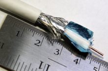
At the start of analog satellite Boob tube broadcasts in the U.k. past Sky, a 75 ohm cable referred to as RG6 was used. This cable had a 1 mm copper core, air-spaced polyethylene dielectric and copper braid on an aluminum foil shield. When installed outdoors without protection, the cablevision was affected by UV radiation, which cracked the PVC outer sheath and allowed moisture ingress. The combination of copper, aluminum, moisture and air caused rapid corrosion, sometimes resulting in a 'snake swallowed an egg' appearance. Consequently, despite the higher cost, the RG6 cable was dropped in favor of CT100 when Sky launched its digital broadcasts.
From around 1999 to 2005 (when CT100 manufacturer Raydex went out of business), CT100 remained the 75 ohm cable of selection for satellite TV and especially Heaven. It had an air-spaced polyethylene dielectric, a 1 mm solid copper cadre and copper complect on copper foil shield. CT63 was a thinner cablevision in 'shotgun' fashion, meaning that it was ii cables molded together and was used mainly by Sky for the twin connectedness required past the Sky+ satellite Television receiver, which incorporated a hard drive recording organization and a 2d, independent tuner.
In 2005, these cables were replaced by WF100 and WF65, respectively, manufactured by Webro and having a like construction but a foam dielectric that provided the aforementioned electrical performance as air-spaced merely was more robust and less likely to be crushed.
At the same fourth dimension, with the price of copper steadily rising, the original RG6 was dropped in favor of a construction that used a copper-clad steel core and aluminum braid on aluminum foil. Its lower price made it attractive to aerial installers looking for a replacement for the so-called low-loss cable traditionally used for Uk terrestrial aerial installations. This cable had been manufactured with a decreasing number of strands of braid, as the cost of copper increased, such that the shielding performance of cheaper brands had fallen to as low as 40 percent. With the advent of digital terrestrial transmissions in the UK, this low-loss cablevision was no longer suitable.
The new RG6 still performed well at loftier frequencies because of the skin consequence in the copper cladding. Even so, the aluminum shield had a loftier DC resistance and the steel core an even higher one. The result is that this type of cable could not reliably exist used in satellite TV installations, where information technology was required to behave a significant corporeality of current, considering the voltage drib afflicted the operation of the low noise block downconverter (LNB) on the dish.
A problem with all the aforementioned cables, when passing current, is that electrolytic corrosion can occur in the connections unless moisture and air are excluded. Consequently, various solutions to exclude wet take been proposed. The first was to seal the connection by wrapping information technology with self-amalgamating rubberized tape, which bonds to itself when activated by stretching. The second proposal, past the American Channel Master company (now owned past Andrews corp.) at least every bit early as 1999, was to apply silicone grease to the wires making connection. The third proposal was to fit a self-sealing plug to the cable. All of these methods are reasonably successful if implemented correctly.
Interference and troubleshooting [edit]
Coaxial cable insulation may dethrone, requiring replacement of the cablevision, especially if it has been exposed to the elements on a continuous ground. The shield is ordinarily grounded, and if even a single thread of the complect or filament of foil touches the center conductor, the point volition be shorted causing significant or total signal loss. This virtually ofttimes occurs at improperly installed end connectors and splices. Also, the connector or splice must exist properly attached to the shield, as this provides the path to ground for the interfering signal.
Despite being shielded, interference can occur on coaxial cablevision lines. Susceptibility to interference has little relationship to broad cablevision type designations (e.g. RG-59, RG-6) only is strongly related to the composition and configuration of the cable's shielding. For cable television, with frequencies extending well into the UHF range, a foil shield is normally provided, and will provide total coverage likewise every bit high effectiveness against high-frequency interference. Foil shielding is usually accompanied by a tinned copper or aluminum complect shield, with anywhere from 60 to 95% coverage. The complect is important to shield effectiveness considering (i) information technology is more effective than foil at preventing low-frequency interference, (2) it provides higher electrical conductivity to basis than foil, and (3) it makes attaching a connector easier and more than reliable. "Quad-shield" cable, using two low-coverage aluminum braid shields and ii layers of foil, is oft used in situations involving troublesome interference, but is less constructive than a single layer of foil and single high-coverage copper complect shield such every bit is plant on broadcast-quality precision video cable.
In the United States and some other countries, cablevision television distribution systems use extensive networks of outdoor coaxial cablevision, often with in-line distribution amplifiers. Leakage of signals into and out of cablevision Tv set systems can crusade interference to cable subscribers and to over-the-air radio services using the aforementioned frequencies as those of the cable system.
History [edit]

Early coaxial antenna feedline of 50 kW radio station WNBC, New York, 1930s
AT&T coaxial cable trunkline installed between Eastward Declension and Midwest in 1948. Each of the 8 coaxial subcables could carry 480 telephone calls or 1 idiot box channel.
- 1858 — Coaxial cablevision used in get-go (1858) transatlantic cable.[47]
- 1880 — Coaxial cable patented in England by Oliver Heaviside, patent no. i,407.[48]
- 1884 — Siemens & Halske patent coaxial cable in Germany (Patent No. 28,978, 27 March 1884).[49]
- 1894 — Nikola Tesla (U.S. Patent 514,167)
- 1929 — Showtime modernistic coaxial cablevision patented by Lloyd Espenschied and Herman Affel of AT&T's Bong Telephone Laboratories.[l]
- 1936 — First airtight circuit transmission of Television pictures on coaxial cable, from the 1936 Summer Olympics in Berlin to Leipzig.[51]
- 1936 — Underwater coaxial cable installed between Apollo Bay, near Melbourne, Australia, and Stanley, Tasmania. The 300 km (190 mi) cablevision can carry one 8.five-kHz broadcast channel and seven telephone channels.[52]
- 1936 — AT&T installs experimental coaxial telephone and idiot box cable between New York and Philadelphia, with automatic booster stations every 10 miles (sixteen km). Completed in Dec, it can transmit 240 telephone calls simultaneously.[53] [54]
- 1936 — Coaxial cable laid past the General Post Office (now BT) between London and Birmingham, providing 40 telephone channels.[55] [56]
- 1941 — First commercial utilize in USA by AT&T, between Minneapolis, Minnesota and Stevens Bespeak, Wisconsin. L1 system with capacity of one Television receiver aqueduct or 480 phone circuits.
- 1949 — On January xi, viii stations on the United states of america E Declension and seven Midwestern stations are linked via a long-distance coaxial cable.[57]
- 1956 — First transatlantic coaxial cable laid, TAT-ane.[58] [59]
- 1962 — 960 km (600 mi) Sydney–Melbourne co-axial cable commissioned, carrying iii x ane,260 simultaneous telephone connections, and-or simultaneous inter-urban center television transmission.[sixty] [61]
Encounter besides [edit]
- Balanced line
- BNC Connector
- LEMO Connector
- Radio frequency ability manual
References [edit]
- ^ Nahin, Paul J. (2002). Oliver Heaviside: The Life, Piece of work, and Times of an Electrical Genius of the Victorian Historic period. ISBN0-8018-6909-9.
- ^ a b Silver, H. Ward N0AX; Wilson, Marker J. K1RO, eds. (2010). "Chapter twenty: Transmission Lines". The ARRL Handbook for Radio Communications (87th ed.). The American Radio Relay League. ISBN978-0-87259-144-8.
- ^ van der Burgt, Martin J. "Coaxial Cables and Applications" (PDF). Belden. p. 4. Archived from the original (PDF) on 28 July 2011. Retrieved 11 July 2011.
- ^ a b c d e "5: Transmission Media". The ARRL UHF/Microwave Experimenter's Manual. Newington, CT: American Radio Relay League. 1990. pp. five.nineteen–five.21. ISBN0872593126.
- ^ a b "CommScope product specifications-LDF4-50A" (PDF). Archived from the original (PDF) on 2017-07-13. Retrieved May 25, 2017.
- ^ Jackson, John David (1962). Classical Electrodynamics. New York: John Wiley & Sons, Inc. p. 244.
- ^ "White Bronze, Copper-Tin-Zinc Tri-metal: Expanding Applications and New Developments in a Changing Landscape" (PDF). National Clan for Surface Finishing. June 2013. Archived (PDF) from the original on 2022-03-06.
- ^ Pozar, David Chiliad. (1993). Microwave Engineering. Addison-Wesley Publishing Visitor. ISBN0201504189.
- ^ Ott, Henry West. (1976). Noise Reduction Techniques in Electronic Systems. ISBN0-471-65726-three.
- ^ Elmore, William C.; Heald, Mark A. (1969). Physics of Waves . ISBN0-486-64926-i.
- ^ Kizer, George Maurice (1990). Microwave communication. Iowa Country Academy Press. p. 312. ISBN978-0-8138-0026-iv.
- ^ "Coax power treatment". Archived from the original on 2014-07-14.
- ^ a b "Why l Ohms?". Microwaves 101. 13 Jan 2009. Archived from the original on xiv July 2014.
- ^ "Coax power handling". Microwaves 101. fourteen September 2008. Archived from the original on 28 Jan 2012.
- ^ Michel van Biezen (2014-10-16), Physics - Due east&M: Electric Potential (fifteen of 22) Potential Exterior 2 Concentric Cylindrical Conductors, archived from the original on 2021-10-xxx, retrieved 2018-09-11
- ^ McManusPhysics (2014-03-31), Finding B field for coaxial wire using Ampere'due south law, archived from the original on 2019-08-eleven, retrieved 2018-09-xi
- ^ Physics Galaxy (2014-07-07), 55. Physics | Magnetic Furnishings | Cocky Inductance of a Coaxial Cable | by Ashish Arora, archived from the original on 2021-10-30, retrieved 2018-09-xi
- ^ "Coaxial Cable Equations Formulas". RF Cafe. Archived from the original on 2012-01-19. Retrieved 2012-01-25 .
- ^ "AESS(TRG) 71181 Part 2, May 1977 Superscreened co-axial cables for the nuclear power manufacture". May 1977.
- ^ "IEC 61917 Cables, cable assemblies and connectors – Introduction to electromagnetic (EMC) screening measurements Showtime edition 1998-06" (PDF). [ permanent expressionless link ]
- ^ "Coaxial Cable Specifications for RG-6". madaboutcable.com. Archived from the original on 2010-08-13. Retrieved 2011-06-28 .
- ^ a b c d e f g h i j thou l one thousand n o p q r s t u v "Times Microwave Coax Loss Calculator". Retrieved 2011-10-26 .
- ^ http://www.dxengineering.com/pdf/Belden%20RG8X%20Date%209258.pdf[ bare URL PDF ]
- ^ "Coaxial Cable Specifications for RG-11". madaboutcable.com. Archived from the original on 2010-08-11. Retrieved 2011-03-29 .
- ^ "Belden 7731A RG11 Coax" (PDF). belden.com. Archived from the original (PDF) on 2018-02-24. Retrieved 2018-02-23 .
- ^ "Coaxial Cable Specifications for RG-58". madaboutcable.com. Archived from the original on 2010-08-09. Retrieved 2011-03-29 .
- ^ "Coaxial Cable Specifications for RG-59". madaboutcable.com. Archived from the original on 2010-08-11. Retrieved 2011-03-29 .
- ^ "Cablevision Velocity Factor and Loss Data". febo.com.
- ^ "Coaxial Cable Specifications for RG-62". madaboutcable.com. Archived from the original on 2010-08-11. Retrieved 2011-03-29 .
- ^ "Coaxial Cable Specifications for RG-178". madaboutcable.com. Archived from the original on 2011-09-28. Retrieved 2011-04-xi .
- ^ "RG178 Mini-Coax".
- ^ "Coaxial Cable Specifications for 5 Core RG-179 (RGBHV)". madaboutcable.com. Archived from the original on 2012-03-30. Retrieved 2011-06-28 .
- ^ http://www.wellshow.com/spec/cable/Harbour-RG188.pdf[ bare URL PDF ]
- ^ "RG195 Coax Cable | Allied Wire & Cable".
- ^ "Coaxial Cable Specifications for RG-213". madaboutcable.com. Archived from the original on 2011-09-26. Retrieved 2011-06-28 .
- ^ "Coaxial Cable Specifications for RG-214". madaboutcable.com. Archived from the original on 2010-10-08. Retrieved 2011-03-29 .
- ^ "Coaxial Cable Specifications for RG-316". madaboutcable.com. Archived from the original on 2010-08-11. Retrieved 2011-06-28 .
- ^ "Coaxial Cable Specifications for RG-400". madaboutcable.com. Archived from the original on 2011-09-28. Retrieved 2011-06-28 .
- ^ http://www.dnd.hu/uploads/termek_doc/Belden_h500pe_en.pdf[ bare URL PDF ]
- ^ "Times Microwave LMR-240 Data Sail" (PDF). Archived from the original (PDF) on 2011-ten-18. Retrieved 2011-10-26 .
- ^ "Radio Urban center Inc". Archived from the original on 2008-12-07. Retrieved 2009-02-06 .
- ^ "Coaxial Cablevision Specifications Cables Chart". RF Cafe. Archived from the original on 2012-01-03. Retrieved 2012-01-25 .
- ^ "Phase Velocity". Microwaves 101. 2010-03-30. Archived from the original on 2012-01-fourteen. Retrieved 2012-01-25 .
- ^ "CommScope Heliax". Archived from the original on 2016-06-28. Retrieved 2016-06-28 .
- ^ "Cablewave Radio Frequency Systems <http://www.rfsworld.com>". Archived from the original on 2007-12-02. Retrieved 2007-12-04 .
- ^ "CommScope Radiax". Archived from the original on 2016-05-30. Retrieved 2016-06-28 .
- ^ "Coaxial cable used in first Transatlantic telegraph cable". Harper's Weekly (38): 447–448. May 12, 1894. ISBN9780801869099.
- ^ Nahin, Paul J. (thirteen November 2002). "3: The First Theory of the Electric Telegraph". Oliver Heaviside. ISBN9780801869099.
- ^ Feldenkirchen, Wilfried (1994). Werner von Siemens - Inventor and International Entrepreneur. ISBN0-8142-0658-1.
- ^ U.Southward. Patent 1,835,031
- ^ "Early Electronic Television - The 1936 Berlin Olympics". earlytelevision.org. Archived from the original on 2007-12-03.
- ^ Huurdeman, Anton A. (31 July 2003). "Copper-Line Manual". The worldwide history of telecommunication. ISBN9780471205050.
- ^ "Coaxial Debut". Time. December 14, 1936. Archived from the original on 2007-10-13.
- ^ "Gallery: An illustrated history of the transoceanic cable". Boing Boing.
- ^ Tozer, Edwin Paul J. (2004). Broadcast engineer's reference book. ISBN9780240519081.
- ^ "Coaxial feeder or RF coax cable". Radio-electronics.com.
- ^ Teachout, Terry. "The New-Media Crunch of 1949". Wall Street Periodical . Retrieved 19 January 2015.
- ^ "1956 TAT-1 Silver Commemorative Dish". Atlantic-cable.com.
- ^ Huurdeman, Anton A. (31 July 2003). The worldwide history of telecommunications. ISBN9780471205050.
- ^ "Australia's Prime Ministers". National Archives of Australia. Archived from the original on four August 2017. Retrieved 14 September 2013.
- ^ The Australasian Engineer. 1962. p. 33.
External links [edit]
- RF Manual Lines and Fittings. Military Standardization Handbook MIL-HDBK-216, U.S. Department of Defence force, 4 January 1962. [one]
- Withdrawal Observe for MIL-HDBK-216 2001
- Cables, Radio Frequency, Flexible and Rigid Details Specification MIL-DTL-17H, 19 August 2005 (superseding MIL-C-17G, 9 March 1990). [2]
- Radio-Frequency Cables, International Standard IEC 60096.
- Coaxial Communication Cables, International Standard IEC 61196.
- Coaxial Cables, British Standard BS EN 50117
- H. P. Westman et al., (ed), Reference Data for Radio Engineers, Fifth Edition, 1968, Howard W. Sams and Co., no ISBN, Library of Congress Menu No. 43-14665
- "What's the All-time Coaxial cable to use for..."
- https://books.google.com/books?id=e9wEntQmA0IC&pg=PA20&lpg=PA20&source=bl&hl=en&sa=X&f=false
- "The Electromagnetic Theory of Coaxial Transmission Lines and Cylindrical Shields". Bong Organisation Technical Journal. xiii (iv). October 1934.
- Brooke Clarke, "Transmission Line Zo vs. Frequency"
Source: https://en.wikipedia.org/wiki/Coaxial_cable
0 Response to "what kind of wire does dish use to antenna"
Post a Comment